


John Breed, Diary and Training diary, item 91
Transcription
Transcription history
-
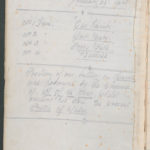
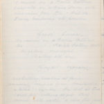
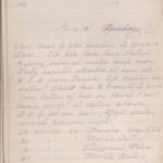
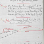
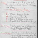
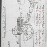
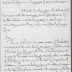
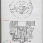
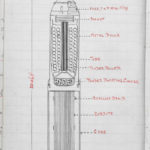
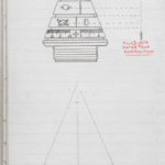
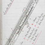
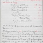
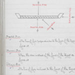
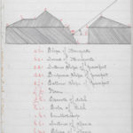
"The Hydraulic Buffer;" Parts for the diagram on the previous page
A = Cap outer Spring case H = {?keep stud retaining G = Stud retaining stuffing bore
B = Case spring Inner { Stuffing box
C = Cylinder J = Plates parting spring outer P Washer } outer Front
D = Gland K = Plates parting spring Inner R Running } - .. - Rear
E = Nut securing cylinder Outer L = Plug filling hole S out } inner Front
F = " " " Inner M = Plunger controlling T springs } - .. - Rear
G = Nut piston rod N = Rod piston
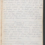
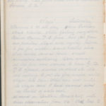
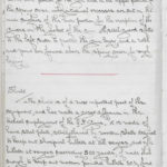
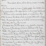
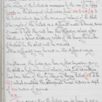
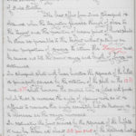
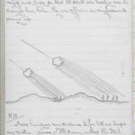
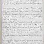
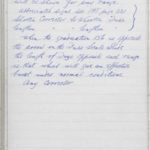
The hydraulic buffer which is contained in a spring
case in the upper portion of the cradle consists of a;
Cylinder, piston, piston-rod, controlling plunger, stuffing
box with gland also 8 running out springs.
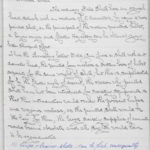
The cylinder is closed at the rear by the controlling
plunger and at the front by the stuffing box and gland
which are locked in the required position by a spring
nut or stud.
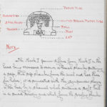
The gun is attached to the cylinder and secured by
two nuts, a number of longitudinal grooves of varying
depth are formed on the inner surface of the cylinder
so that the space for the flow of the liquid between
-
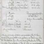
" The Hydraulic Breffer"
A= Cap Outer Spring Case H=inkreep stud retraining G= Stud retraining stuffing base stuffing base
B= Case spring Inner
C= Cylinder J=Crates Parting Spring P Washer outer front
D = Gland K= Crates parting Spring Inner R Running outer rear
-
" The Hydraulic Breffer"
A= Cap Outer Spring Case H=inkreep stud retraining G= Stud retraining stuffing base stuffing base
B= Case spring Inner
C= Cylinder J=Crates Parting Spring P Washer outer front
D = Gland K= Crates parting Spring Inner R Running outer rear
Description
Save descriptionLocation(s)
- ID
- 17035 / 198330
- Contributor
- Mrs Jean Hanby
Login to edit the languages
Login to edit the fronts
- Western Front
Login to add keywords
- Artillery
- Trench Life
Notes and questions
Login to leave a note
would be better if we could add columns to this